NCERT Notes for Class 10 Science Chapter 10 Reflection and Refraction
CBSE Class 10 Science notes will assist students in studying the topic thoroughly and clearly.
These CBSE Class 10 Science notes were written by subject experts who made the study material very basic, both in terms of language and format.
Reflection of Light
Reflection of light is the phenomenon of light rays refracting back into the same medium after colliding with a smooth surface.
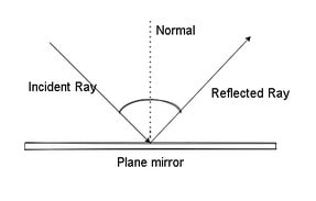
Laws of Reflection
Reflection is governed by two laws:
(i) The incidence angle is always equal to the reflection angle, i.e. <i = <r.
(ii) At the point of incidence, the incident ray, the reflected ray, and the normal all lie in the same plane.
Image
If light rays emanating from a point meet or seem to meet at another point after reflection, the second point is referred to as the image of the initial point.
Real Image
If light rays coming from a point truly collide after reflection, the resulting picture is referred to as a real image.
Virtual Image
If the light rays emanating from a location do not really meet but seem to do so at another point, the picture generated is referred to as a virtual image.
Mirror
A mirror is a polished surface that reflects almost all of the light that hits it. There are two sorts of mirrors:
Plane Mirror
If a mirror’s reflecting surface is flat, the mirror is referred to as a plane mirror. A plane mirror’s image has the following properties:
- It is perpetually virtual and upright.
- The picture is equal to the size of the item.
- The image’s distance from the mirror is equal to the object’s distance from the mirror.
- The picture is flipped laterally, so that left seems to be right and vice versa.
Uses of Plane Mirrors
Plane mirrors are often used as looking glasses, in the construction of kaleidoscopes and periscopes, among other things.
Spherical Mirror
If the mirror’s reflecting surface is curved inwards or outwards, the mirror is referred to as a spherical mirror. There are two kinds of spherical mirrors:
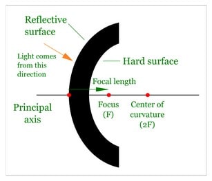
- A concave mirror is a spherical mirror with an inward curved reflecting surface. After reflection off such surfaces, a beam of light often converges, which is why it is sometimes referred to as a convergent mirror.
- e.g. A sparkling spoon’s inside curving surface may be thought of as a concave mirror.
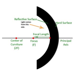
- A convex mirror is a spherical mirror with an outward curved reflecting surface. Because a beam of light often diverges after being reflected by this surface, it is sometimes referred to as a diverging mirror.
- e.g. The convex surface of a dazzling spoon’s outer curving surface may be regarded or viewed as a convex mirror.
Some Definitions Related to Spherical Mirrors
Centre of Curvature
- A spherical mirror’s centre of curvature is the centre of the imaginary sphere of which the mirror is a part.
- It is denoted by the letter C in the preceding figures. The centre of curvature of a concave mirror is in front of it, while the centre of curvature of a convex mirror is behind it.
Radius of Curvature
- The radius of curvature of a spherical mirror is equal to the radius of the imaginary sphere comprising the mirror.
- It is denoted by R in the preceding picture.
Pole
- The spherical mirror’s pole is defined as the midpoint of its reflecting surface.
- It is denoted by P in the preceding picture.
Principal Axis
- A spherical mirror’s major axis is the line connecting the pole with the centre of curvature.
- PC is the primary axis shown in the illustration.
Aperture
- The diameter of a spherical mirror’s reflecting surface is referred to as its aperture. It is the portion of a mirror’s reflecting surface that is exposed to incident light.
- It equals the straight line distance between the mirror’s two ends. M₁ M₂ is the aperture of the mirror in the illustration.
Principal Focus of a Spherical Mirror
- It is the point on the mirror’s primary axis at which light rays travelling parallel to the principal axis actually meet after reflection. It is denoted by the letter F.
- The focus of a concave mirror is in front of the mirror, while the focus of a convex mirror is behind the mirror.
- A concave mirror’s focus is physical, while a convex mirror’s focus is imaginary.
Focal Length
- The focal length of a spherical mirror is the distance between its pole and major focus. It is denoted by f. If the mirror’s aperture is tiny, then f = R/2.
- That is, the primary focus of a spherical mirror is located halfway between the pole and the centre of curvature.
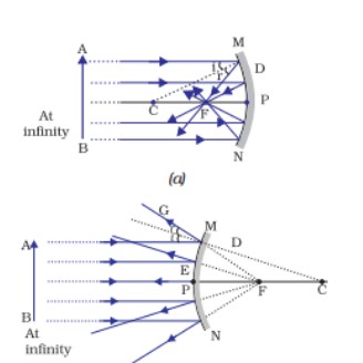
Representation of Images Formed by Spherical Mirrors Using Ray Diagrams
Everywhere, light is reflected according to the same two rules. When creating a ray diagram to find an object’s image, it is more convenient to consider just two rays.
At least two reflected rays must meet to determine the location of the point object’s picture.
The following rays may be considered for determining the image’s location.
- Rays parallel to the major axis flow through the focus in a concave mirror after reflection or seem to originate from the focus in a convex mirror.
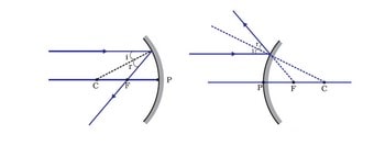
- After reflection from the mirror, the rays passing through the focus of a concave mirror or approaching the focus of a convex mirror become parallel to the primary axis.
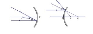
- A ray hitting a concave mirror’s centre of curvature or a convex mirror’s centre of curvature reflects back along the same path.
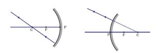
- A ray incident obliquely to the major axis and directed toward a concave or convex mirror’s pole P is reflected obliquely according to reflection rules. Specifically, <i=<r.
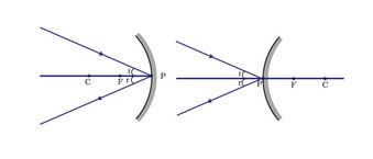
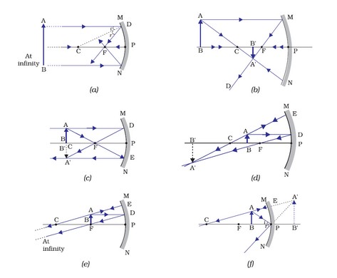
IMAGE FORMATION BY SPHERICAL MIRRORS
Image Formation by a Concave Mirror
- The table below displays the ray diagram in conjunction with the location and type of the picture created by a concave mirror at different object placements.
Uses of Concave Mirrors
- Concave mirrors are often used in flashlights, searchlights, and car headlights to produce intense parallel beams of light.
- Concave mirrors are utilised as shaving mirrors because they provide for a more detailed view of the face.
- Dentists use concave mirrors to get big photographs of their patients’ teeth.
- In a solar furnace, enormous concave mirrors are utilised to focus sun rays on a spot, producing a tremendous quantity of focused heat.
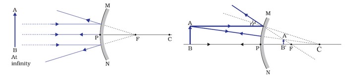
Image Formation by a Convex Mirror
Two locations of the item are considered while examining the picture created by a convex mirror. Initially, when the item is at infinity, and then when it is a limited distance from the mirror.
The table below demonstrates the ray diagrams, as well as the location and type of the image generated by the convex mirror, for the object’s bottom two places.
Uses of Convex Mirrors
- Convex mirrors are often used as rear view mirrors in automobiles because they always provide an upright picture and offer a broader field of vision due to their outward curvature.
- By using large convex mirrors as store security mirrors, the shop owner can keep an eye out for burglars and shoplifters among the consumers.
Sign Convention for Reflection by Spherical Mirrors
When discussing light reflection by spherical mirrors, we will use a set of sign conventions termed the new Cartesian sign convention based on cartesian coordinates.
The mirror’s pole (P) is assumed to be the origin in this convention. The primary axis of the mirror serves as the coordinate system’s X-axis.
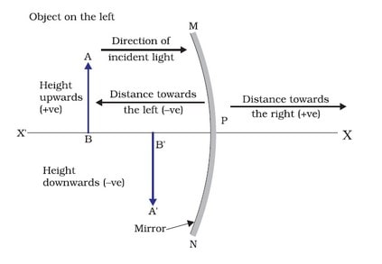
The following conventions apply:
(i) Always position the item to the left of the mirror.
(ii) All parallel to the major axis X-axis) lengths are measured from the mirror’s pole.
(iii) Distances to the left of the pole are negative (-ve X-axis). Positive distances are those to the right of the pole (+ve X-axis).
(iv) Distances above the primary measured perpendicularly (along the + Y-axis) are considered positive.
(v) Negative values are assigned to distances measured perpendicular to the primary axis (along the – Y-axis).
Additionally, the focal length of a convex mirror is assumed to be positive, while the focus length of a concave mirror is assumed to be negative.
Mirror Formula
- The object distance (u) is the distance between an object and its pole in a spherical mirror .
- The image distance (v) is the distance between the picture and the mirror’s pole .
- The focal length (f) is the distance between the primary focus and the pole.
- The mirror formula is the relationship between the quantities u, v and f.
- It is denoted as 1/v + 1/u + 1/f
- where u, v and f are to be used in accordance with their newly established cartesian sign conventions.
- This formula holds true in all cases for all spherical mirrors and all object placements.
Magnification by Spherical Mirror
Magnification created by a spherical mirror indicates the amount to which an object’s image is amplified in relation to its size.
It is represented as the ratio of the image’s height to the object’s height. It is denoted by m.
i.e. Magnification, m = – (Height of image / Height of object ) or
Magnification is also linked to the object’s distance from the camera (u) and the image’s distance from the camera (v). It might be stated as
m = Image distance (v) / Object distance (u) = -v/u
where u and v need to be utilised appropriately. The magnification of a mirror or lens indicates the size of the image in relation to the object.
| Magnification | Size of Image (hi) |
| m = 1 | hᵢ = h₀ |
| m < 1 | hᵢ < h₀ |
| m > 1 | hᵢ > h₀ |
The degree of magnification imparted by a mirror or lens reveals the nature of the picture created.
| Sign of Magnification | Image |
| -ve | Real and inverted |
| +ve | Virtual and erect |
Identification of Mirrors
The nature of an item may be determined by viewing the pictures created by a mirror at various locations.
- If the mirror’s image is the same size as the item at various locations, the mirror is a plane mirror.
- If the mirror’s image is decreased in all locations of the item, the mirror is convex.
- A concave mirror is one in which the image generated behind the mirror is longer than the item.
Refraction of Light
- The change in the course of a light beam as it goes from one medium to another is referred to as refraction of light.
- When light travels from a rarer to a denser medium, it bends toward the normal (i > r), and when light travels from a denser to a rarer medium, it bends away from the normal (i < r), where i equals angle of incidence and r equals angle of refraction.
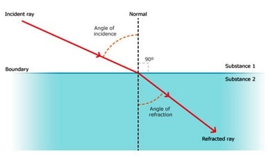
Cause of Refraction
Light travels at a variable speed in various media, being faster in rarer media and slower in denser media.
Thus, when light enters a denser medium, its speed decreases and it bends toward the normal, while entering a rarer medium, its speed rises and it bends away from the normal.
Examples of Refraction of Light
- The bottom of a pond or tank filled with water seems to be lifted because of light refraction when light rays flow through the pool of water and into the air.
- Due to light refraction, the letters seem to be elevated when seen through a glass slab placed over the page.
- A pencil that is partly submerged in water looks bent due to the refraction of light from the submerged portion of the pencil.
- When seen from the sides, a lemon maintained in water in a glass tumbler looks to be larger than its true size.
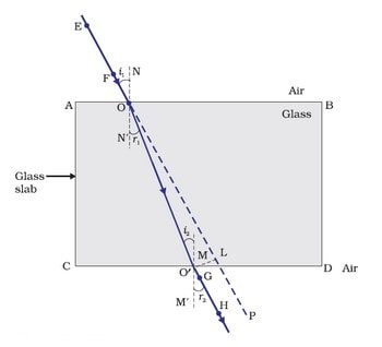
Refraction through a Rectangular Glass Slab
When a light ray passes through a glass slab, the emerging ray is parallel to the incident ray but slightly displaced to the side.
In this situation, refraction occurs twice: first when the ray enters the glass slab from the air and again when it departs the glass slab to the air.
Both refractions are shown in the image (glass slab is the denser medium, while air is the rarer media).
The angle of bending of the light beam is equal and opposing at the opposite parallel sides AB and CD of a rectangular glass slab. As a result, the ray emanating from face CD is parallel to the incident beam but slightly moved to the side.
When i denotes the angle of incidence, r = refraction angle and e denotes the angle of emergence.
Lateral Displacement – When light travels through a glass slab, the perpendicular distance between the emerging and incident rays is referred to as lateral displacement.
Laws of Refraction
Light refracts as per the following laws:
(i) At the point of incidence, the incident ray, the refracted ray, and the normal to the interface of two transparent media all lie in the same plane.
(ii) For a given pair of media, the ratio of the sine of the incidence angle to the sine of the refraction angle is constant (Snell’s law). It is denoted as
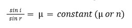
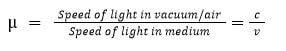
This constant is referred to as the refractive index (μ)
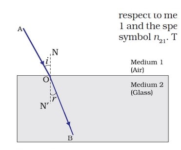
Refractive Index
The refractive index indicates the magnitude of the direction shift that occurs between two mediums.
1μ 2 denotes the refractive index of medium 2 in comparison to medium 1, as light passes through medium 1 and into media 2.
![]()
The refractive index of a medium in relation to vacuum is referred to as its absolute refractive index. A medium’s absolute refractive index is simply referred to as its refractive index.
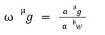
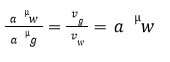
For a pair of glass and water,
Refractive Index and Speed of Light
If c denotes the speed of light in air and v denotes the speed of light in a medium, then the medium’s refractive index is
 Thus, for any two media, the refractive index of the second medium is equal to the ratio of the light velocities in the two media.
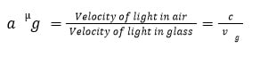
Glass’s refractive index in relation to air,
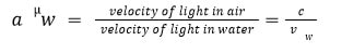
Water’s refractive index in comparison to air,
We get by dividing Eq. (ii) by Eq. (i)
Lens
A lens is a transparent medium that is limited by two spherical surfaces, one or both of which are spherical. There are two kinds of lenses:
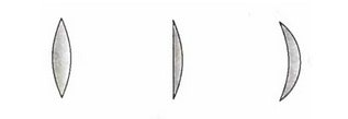
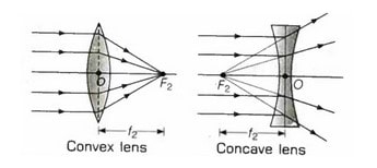
Convex or Converging Lens
A convex lens is one that is thicker in the centre and narrower at the ends. Convex lenses are classified into three categories, as seen below:
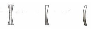
Concave or Diverging Lens
A concave lens is one that is narrower in the centre and thicker at the ends. Concave lenses are classified into three categories, as seen below:
Some Definitions Related to Lenses
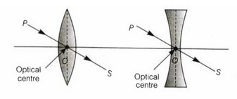
Optical Centre : The optical centre of a lens is its optical centre. It is denoted by 0.
The optical centre of a lens is a point toward which incoming rays refract without deviating from their course.
Centres of Curvature : The centres of the two imaginary spheres of which the lens is a portion are referred to as the lens’s centres of curvature.
It is denoted by C. A lens has two curvature centres in relation to its two curved surfaces.
Radii of Curvature : The radii of the two imaginary spheres that comprise the lens are referred to as the lens’s radii of curvature.
A lens has two curvature radii. These could or might not be equivalent.
Principal Axis : The imaginary line connecting the two centres of curvature of a lens is referred to as the primary axis.
Additionally, the optical centre is located on the principal axis.
Principal Focus : The lens has two primary focus:
(i) First Principal Focus – This is a point on the lens’s principal axis at which the rays emanating from or directed toward the lens become parallel to the principal axis after refraction.
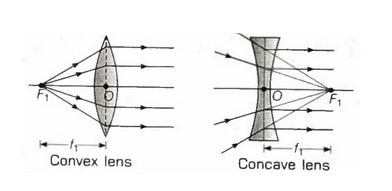
(ii) The second Principal Focus is the point on the principal axis at which parallel rays converge on the opposite side of the lens (convex) or seem to meet onthe same side of the lens (concave), after lens refraction.
Both convex and concave lenses have a true focus, while concave lenses have a virtual focus.
Focal Length of Lens : The distance between the lens’s focus and optical centre is referred to as the focal length of the lens.
Focal Plane : The focal plane is the plane that passes through the focus and is perpendicular to the primary axis.
Aperture : The aperture of a spherical lens is the effective diameter of its circular shape.
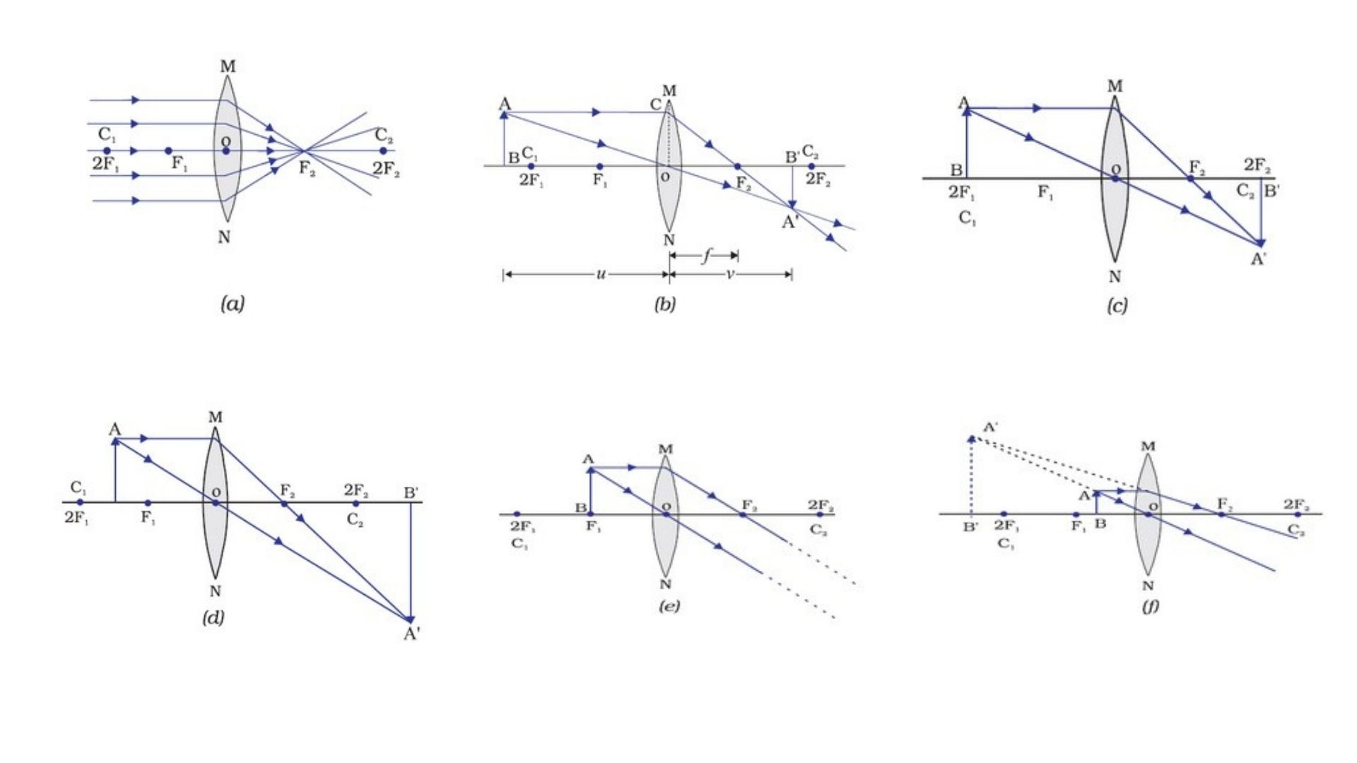
Image Formation in Lenses Using Ray Diagrams
- We may see the generation of images via lenses using ray diagrams:
- We consider any two of the following rays when constructing ray diagrams in lenses similar to spherical mirrors.
(i) After refraction, parallel to the primary axis rays pass through the principal focus in the case of a convex lens and seem to be coming from the main focus in the case of a concave lens.
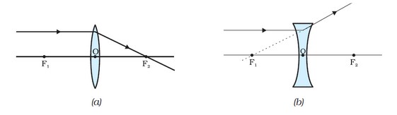
ii) A ray that passes through or is directed toward the focus emerges parallel to the primary axis.
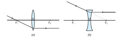
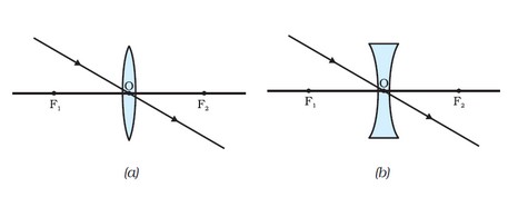
iii) A ray directed toward an optical center will emerge unaltered.
Formation of Image by a Convex Lens
The table below demonstrates the ray diagrams, as well as the location and type of the picture created by the convex lens at different object placements.
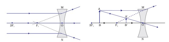
Formation of Image by a Concave Lens
Two object locations are examined while examining the picture produced by concave lens. Initially, when the item is at infinity, and then when it is at a limited distance from the lens.
The table below demonstrates the ray diagrams, as well as the location and type of the picture generated by the concave lens, for the object’s top two places.
Sign Convention for Spherical Lenses
Lenses are denoted in the same way that mirrors are. Additionally, convex lenses have a positive focal length, while concave lenses have a negative focal length.
Lens Formula
- This equation establishes a link between the object distance (u), the image distance (v), and the focal length (f).
- The lens formula is as follows: 1/v + 1/u = 1/f
- The lens formula is universal and applies to any spherical lens under all circumstances.
Magnification by Lenses
- Magnification (m) is the ratio of the image’s height (hi) to the object’s height (ho)
- Magnification – m = hᵢ/hₒ or m = v/u
- When a virtual picture is generated, magnification is positive; when a real image is formed, linear magnification is negative.
Power of a Lens
- The capacity of a lens to focus or diverge light rays is referred to as the lens’s power (P). It is the reciprocal of the focal length.
- i.e. P = 1/ f (in metre)
- It is denoted by the SI unit dioptre (D) (1 D = 1 m⁻¹).
- If f is in metres, then power is in dioptres. Thus, dioptre refers to the strength of a lens with a focal length of one metre. If the focal length is specified in centimetres,
- power = 100 / f (in cm)
- Power and focal length are negative for concave lenses. Power and focal length are positive for convex lenses.