NCERT Notes for Class 10 Science Chapter 12 Electricity
CBSE Class 10 Science notes will assist students in studying the topic thoroughly and clearly.
These CBSE Class 10 Science notes were written by subject experts who made the study material very basic, both in terms of language and format.
Electric Charge and Current
Electric Charge
Excess or lack of electrons on a body defines a charge.
If an object gains electrons, it is said to be negatively charged. e.g.
Negative charge is created when an ebonite rod is brushed with fur. If a body loses electrons, it is considered to be positively charged. A glass rod brushed with such a silk fabric, for example, gains a positive charge.
Coulomb is the SI unit for electric charge (C).
A body’s overall charge is equal to an integral multiple of the charge on a single electron. Quantisation of charge is the name for this principle.
- e = – 1.6 X 10⁻¹⁹ C is the magnitude of charge on one electron.
- q = ne = n X 1.6 X 10⁻¹⁹ C, charge on n electrons.
- e =+ 1.6 X 10⁻¹⁹ C is the magnitude of charge on one proton.
Electric Current
It’s the rate at which electric charge flows through any cross-section of a conductor in one unit of time.
If q charges pass through a conductor in t seconds, then
Electric charge(I) = Charge(q) / Time(t) = ne/t [·: q = ne]
where n is the number of electrons passing through a conductor.
The ampere (A) is the SI unit of electric current, named for French scientist Andre-Marie Ampere (1775-1836). It’s a number with a scalar value.
The electric current flowing through any cross-section of a conductor is stated to be 1 ampere when 1 coulomb of charge flows through it in 1 second.
i.e. 1 ampere =1 coulomb / 1 second ⇒ 1A = 1C / 1S
Milliampere (1A = 10⁻³ A ) and microamperes (1μ = 10⁻⁶ ) are smaller units of current.
Direction of Electric Current
The movement of electrons (negative charges) is considered to be in the opposite direction of electric current. Current flows from the positive terminal of the cell to the negative terminal in an electric circuit.
Flow of Charges Inside a Wire
Although the atoms in a solid are packed very closely together, electrons are able to move through the solid crystal as if it were a vacuum.
When a steady current flows in a conductor, the electrons in it move at a constant speed of the order of 10⁻⁴ m/s (the constant speed of the electrons inside the conductor as they move under the influence of external electric supply).
In a wire, current is produced by the flow of charges (i.e. electrons).
Electric Potential and Potential Difference
Electric Potential
It’s the amount of labour that goes into moving a unit positive charge from infinity to a point.
If work done in moving a positive charge q from infinity to a point is W, then electric potential V of that point is
V = W/q
The volt M is a SI unit of electric potential named after Italian physicist Alessandro Volta (1745-1827). It’s a number with a scalar value.
Electric Potential Difference (ᐃ ˅)
It is defined as the amount of work required to move a unit positive charge from one position to another.
If 1 joule of work is expended in transporting 1 coulomb of electric charge from one location to another, the electric potential difference between the two points is said to be 1 volt.
Thus, I volt = 1 joule / 1 coulomb
⇒ 1 V = 1 J / 1 C
⇒ 1 V = 1 J/C = 1 J C-1
Smaller units of electric potential,
1 mV = 10⁻³ V , 1 μV = 10⁻⁶ V
Larger units of electric potential,
1 kV = 10³ V , 1 MV = 10⁶ V
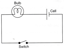
Electric Circuit
Electric circuit is a closed and continuous route through which electric current passes. It consists of a current source (such as a cell or battery), a load (such as a bulb or any other ocher appliance), a switch/key (to open or close a circuit), and a fuse, all of which are connected by connecting wires. Copper is commonly used for these wires.
When the key is pressed, the circuit is said to be closed. This indicates that a constant current would flow through the circuit to power the item.
The circuit is called an open circuit when the key is open. This prevents current from flowing through the circuit.
Circuit Diagram
It’s a diagram that shows the relative positions and connections of various circuit components, which are represented by symbols.
Ohm’s Law
Georg Simon Ohm (1787-1854), a German physicist, proposed this law in 1827. It establishes a link between the current / flowing through a metallic wire and the potential difference V between its terminals.
The electric current flowing through a conductor is directly proportional to the potential difference supplied across its ends, assuming that the physical circumstances (such as temperature) stay constant.
According to Ohm’s law, if V is the potential difference applied across the ends of a conductor through which current I flows, then
V ∝ I [at constant temperature]
or, V = IR or I = V/R
where, R is the constant of proportionality called resistance of the conductor at a given temperature.
Current is inversely proportional to resistance, as shown by the formula above. Current is halved when resistance is doubled, and current is doubled when resistance is halved.
V-/Graph
For ohmic (metal) conductors, the graph between the potential difference V and the corresponding current I is found to be a straight line passing through the origin.
Resistance
The property of a conductor that opposes/resists the flow of charges through it is called ft. The ohm is the SI unit for resistance and is represented by the Greek letter Ω .
Resistance of a conductor is given by,
R= V/I
If a potential difference of 1 volt across the ends of the conductor causes a current of 1 ampere to flow through it, it is said to be 1 ohm.
1 ohm = 1 volt / 1 ampere
1 Ω = 1V / 1A = 1 VA⁻¹
Some Important Terms Related to Resistance
The following are some key terms linked to resistance:
- Resistor: A resistor is a component in an electric circuit that provides resistance to the flow of electrons that make up electric current. These are used to construct electrical devices that require a high level of resistance. Alloys like nichrome, manganin, and constantan, for example, lower current in a circuit.
- Rheostat/variable resistance: It is a variable resistor that is used to manually increase or decrease the resistance to control the flow of electric current.
- Good conductor: A good conductor is a substance that has a low resistance to the flow of electrons or electric current in an electric circuit, such as silver, copper, or aluminium. Silver is the finest conductor of electricity among these.
- Poor conductor: A poor conductor is a material that has a higher resistance to the flow of electrons or electric current in an electric circuit than conductors, such as mercury, lead, stainless steel, and iron and chromium alloys.
- Insulator: Insulators, such as rubber, dry wood, and plastic, provide extremely high resistance to the flow of electrons or electric current in an electric circuit. They don’t have any electric current flowing through them.
Factors on which the Resistance of a Conductor Depends
A conductor’s electrical resistance is determined by the following factors:
(i) Length of the conductor: The resistance of a conductor R is proportional to the length l of the conductor.
i.e. R ∝ l …….(i)
Because a wire’s resistance is proportional to its length, when the wire’s length is doubled or halved, the resistance is similarly doubled or halved.
(ii) Area of cross-section of the conductor: r A conductor’s resistance R is inversely proportional to its cross-sectional area A.
i.e. R ∝ 1/A …….(ii)
Because the resistance of a wire is inversely proportional to its cross-sectional area, when the cross-sectional area of the wire is doubled, the resistance is halved, and when the cross-sectional area of the wire is halved, the resistance is doubled.
(iii)Nature of the material of the conductor:The nature of the material from which a conductor is formed determines its resistance. Some materials have a low density.
Others have a lot of resistance, while others have a lot of resistance.
Therefore, from Eqs. (i) and (ii), we can write
R ∝ l/A or, R ∝ ρ l/A
where, ρ is the constant of proportionality and is called resistivity or specific resistance of the conductor.
Resistivity
It’s defined as the resistance of a conductor with a unit length and cross-sectional area. The ohm-metre is its SI unit (Ω.m).
The resistivity of a material is determined by the nature of the substance and the temperature, not by its length or thickness. It is a property of the conductor’s material that changes only when the temperature of the conductor changes.
Insulators such as ~lass, rubber, ebonite, etc., have a very high resistivity (10¹² to 10¹⁷ Ω.-m), while conductors have a very low resistivity (10⁻⁸ to 10⁻⁶ Ω. – m).
Alloys have a higher resistivity than the metals that make them up. They don’t easily oxidise at high temperatures, which is why they’re employed in the heating components of devices like electric irons and heaters.
Tungsten is nearly exclusively utilised in electric bulb filaments, while copper and aluminium are commonly used in electrical transmission lines.
Resistance of a System of Resistors
In order to achieve the desired equivalent resistance in a circuit, two or more resistors can be connected to each other using various combinational methods. The resistors can be connected using one of two approaches, as shown below:
Resistors in Series
Two or more resistors are said to be connected in series when they are connected end to end to each other. The series connection of resistors is shown in the diagram below.
An applied potential V produces current I in the resistors and R₁ , R₂ and R₃ causing a potential drop V₁, V₂ and V₃ respectively, through each resistor.
Total potential, V = V₁ + V₂+ V₃
By Ohm’s law, V₁ = IR₁,
V₂=IR₂ and V₃ = IR₃
Thus, V = V₁ + V₂ + V₃ = IR₁ + IR₂+ IR₃
⇒ V = I (R₁ + R₂ + R₃)
If R is the equivalent resistance and V= IR
Hence, IR = I (R₁ + R₂ + R₃)
⇒ R = R₁ + R₂ + R₃
The following are some key factors to remember while using resistors in series:
- The following are some key factors to remember while using series resistors
- As a result, the equivalent resistance is greater than either resistor’s resistance. Maximum effective resistance is another name for this.
- The current through each resistor is same
- Each resistor has a different potential difference.
Disadvantages of Series Combination
(i) If any of the components fails to work in this combination, the circuit will break and none of the components will work.
(ii) A lamp and a heater cannot be connected in series because they require different current values to function properly.
Resistors of Parallel
When two or more resistors are connected between two points at the same time, they are said to be in series joined in a parallel arrangement.
The parallel connection of resistors is shown in the diagram below.
An applied potential V produces current I₁ in R₁ , I₂ in R₂ and I₃ in R₃ ,
Total current , I= I₁ + I₂ + I₃ ……..(i)
By Ohm’s law , I₁ = V/R₁, I₂= V/R₂, I₃ = V/R₃
If R is the equivalent resistance, then I =V/R
Thus, V/R = V/R₁ + V/R₂ + V/R₃ …….From eq (i)
⇒ V/R= V [ 1/R₁ + 1/R₂ + 1/R₃ ]
⇒ 1/R = 1/R₁ + 1/R₂ + 1/R₃
The following are some key points to remember while using parallel resistor combinations:
- The sum of the reciprocals of individual resistances equals the reciprocal of equivalent resistance.
- Both resistors have a resistance that is less than the corresponding resistance. Minimum effective resistance is another term for this.
- The current from the source is greater than the current through either resistor.
- Each resistor has the same potential difference.
Applications of Parallel Combination in Daily Life
Because the circuits used in daily life comprise components of varied resistances demanding different amounts of current, a parallel combination of resistances is quite beneficial.
This form of circuit combination splits the current among the components (electrical devices) so that they have the right quantity of current to function.
This is why electrical equipment on a domestic circuit are connected in a parallel configuration.
Problem-Based on Combination of Resistors (Series and Parallel Both)
In this combination, some resistances are coupled in series and others are connected in parallel. Complex circuit is another name for this type of combination.
The following are some examples that will assist you in answering questions about resistances in series and parallel.
Heating Effect of Electric Current
The source of electrical energy is a cell or a battery. A potential difference is created inside them as a result of chemical reactions, which is responsible for the Flow of current through any circuit.
The source of electrical energy is a cell or battery. A potential difference is created inside them as a result of chemical reactions, and this is what causes current to flow slowly in any circuit.
The rest can be expiated by boosting the temperature of the equipment in the tr area.
Calculation of Heat Generated in a Conductor
Assume a conductor is a resistance wire that prevents current from flowing through it. As a result, work must be done by the current source in order for the current to flow continuously.
Now we’ll figure out how much work the source does when current I passes via a wire with resistance R. When an electric charge q goes in the direction of a potential difference V ,
Amount of work, W = q × V ……..(i)
From definition of current, we know that,
I = q/t or, q = I × t ………(ii)
From Ohm’s law, V/I =R or, V = IR ………(iii)
Substituting the values of q and V in Eq. (i), we get
W = (I × t) × IR =I²Rt
Assumes that every electrical effort or energy used is transformed into heat energy, i.e. heat generated. As a result, heat is created.
H = I² × R × t
Thus, it is known as Joule’s law of heating.
According to this law, heat produced in a resistor is
- For a given resistance, exactly proportional to the square of current
- Directly proportional to the resistance for a given current.
- The time it takes for the current to pass through the resistor is directly proportional to the time it takes for the current to flow through the resistor.
Practical Applications of Heating Effect of Electric Current
Despite the fact that the heating effect of electric current results in an unwanted loss of electrical energy, it has several practical applications. Below are a few of them.
Electric Bulb
Tungsten filament is used in its construction. Because of its high resistivity and melting point, the majority of the power consumed by this is dispersed as heat, with a small portion converted to light.
To extend the filament’s life, the filament is thermally insulated and the bulb is filled with chemically inactive nitrogen and argon gas.
Electric Fuse
In residential circuits, it serves as a safety device. It safeguards circuits by interrupting the flow of any excessively high electric current. It is connected to the mains supply in series. It is made up of a lead and tin alloy with the proper melting point.
When the circuit’s current exceeds the safe limit, the temperature of the fuse wire rises, the fuse wire melts, and the circuit is broken.
This protects the other circuit elements from the dangers of high current.
Fuses are always rated for various current values, such as 1 amp, 2 amps, 5 amps, 10 amps, 15 amps, and so on.
Electric Power
It is defined as the quantity of electric energy spent per unit time in a circuit.
The electric power is given by if W is the quantity of electric energy utilised in a circuit in t seconds.
P = W/t
But W = electric energy = Vq =VIt [·: q = lt]
P = VIt/t ⇒ ρ = VI
According to Ohm’s law, v = ir
p = IR x I = I²R
⇒ V²/R [ putting I = V/R ]
The watt is the SI unit of electric power (W).
If 1 ampere current runs across a circuit with a 1 volt potential difference, it is considered to be 1 watt.
1 watt = 1 volt × 1 ampere = 1 VA